Aluminium CNC Machining
3, 4 and 5-axis milling and turning of 6061-T6, 6082-T6, 7075-T6 and 5083 parts, anodised or as machined
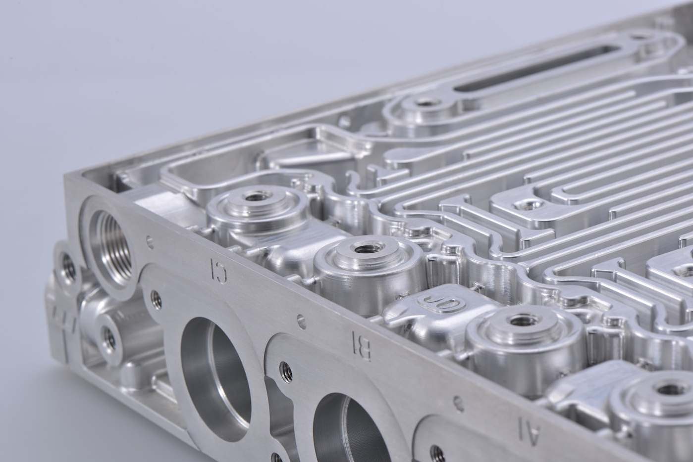
Aluminium CNC machining is the fastest route to accurate, light, corrosion-resistant parts: housings, heat sinks, brackets, manifolds, jigs and prototypes. CutLinq quotes 3, 4 and 5-axis milling and CNC turning of 6061-T6, 6082-T6, 7075-T6 and 5083 from workshops in Egypt, the UAE and Saudi Arabia, with anodising or powder coating included when you need it. Upload a STEP file and receive a binding quote within 12 hours.
The page covers alloy selection, achievable tolerances and surface finish, machine envelopes, finishing options that survive Gulf heat and salt air, and the design details that reduce machining time and therefore price.
Choosing the alloy for machining
6061-T6 and its European twin 6082-T6 are the default: good strength (yield 240 to 260 MPa), excellent machinability, weldable, anodisable and available as plate up to 150 mm and bar up to 300 mm. 7075-T6 nearly doubles the strength (yield 460 to 500 MPa) for aerospace-style brackets and tooling, but it is not weldable, anodises with a slight yellow tone and costs roughly 60 to 100% more than 6061. 5083-H111 is the marine grade for parts on boats and coastal installations; it machines with more burr and is softer, so tolerances open up. 2024-T3 is used where fatigue strength matters but corrodes in salt air unless coated. Cast plate (for example 5083 cast tooling plate) is stress-relieved and stays flat after heavy pocketing, which matters for large fixture plates.
| Alloy (EN AW) | Yield strength | Machinability | Weldable | Anodising result | Relative cost |
|---|---|---|---|---|---|
| 6061-T6 / 6082-T6 | 240 to 260 MPa | Excellent | Yes | Clear, uniform | 1.0 |
| 7075-T6 | 460 to 500 MPa | Very good | No | Slight yellow tint | 1.6 to 2.0 |
| 5083-H111 | 125 to 145 MPa | Fair, burrs | Yes | Good, grey | 1.1 |
| 2024-T3 | 290 to 320 MPa | Very good | No | Poor, needs coating | 1.5 |
| 5083 cast plate | 110 to 130 MPa | Very good, stays flat | Yes | Good | 1.3 |
Tolerances and surface finish
Aluminium machines fast and cleanly, so standard tolerance is ISO 2768-m (±0.1 mm for 6 to 30 mm, ±0.2 mm for 30 to 120 mm), with ±0.05 mm on called-out features at no significant extra cost and ±0.01 to ±0.02 mm on bores and datums when specified. Thermal expansion is 23 µm per metre per °C, about twice steel; a 500 mm part measured at 35 °C in a Dubai workshop is 0.17 mm longer than at 20 °C, so critical parts are inspected in an air-conditioned room. Surface finish as milled is Ra 1.6 to 3.2 µm; a finishing pass gives Ra 0.8 µm; bead blasting then anodising gives a uniform matt look that hides tool marks.
| Feature | Standard | Tight | Notes |
|---|---|---|---|
| Linear dimensions | ±0.1 mm (ISO 2768-m) | ±0.02 mm | Tight only on drawn features |
| Bore diameter H7 | ±0.02 mm up to 50 mm | ±0.01 mm | Reamed or bored |
| Flatness | 0.05 mm per 100 mm | 0.02 mm per 100 mm | Cast plate for large parts |
| Position of holes | ±0.1 mm | ±0.03 mm | Single setup |
| Surface roughness | Ra 3.2 µm | Ra 0.8 µm | Ra 0.4 µm by polishing |
| Thread M3 to M12 | 6H | 6H | Helicoil insert recommended for repeated assembly |
Machine capacity in the network
Vertical 3-axis machining centres with tables of 500 x 400 mm to 1500 x 800 mm cover most housings and plates. 4-axis machines add rotary indexing for parts with features on several faces, and 5-axis simultaneous milling handles impellers, angled ports and complex brackets in one setup. CNC lathes with bar feeders turn round parts from 5 to 65 mm bar automatically, and chucking lathes reach 400 mm diameter. Parts larger than 1500 mm are possible on a small number of gantry machines in the region; ask before designing.
- 3-axis milling: parts up to 1500 x 800 x 500 mm, most economical
- 4-axis: rotary indexing for multi-face parts up to 300 mm diameter
- 5-axis: single-setup complex geometry, best accuracy between features
- Turning: bar work 5 to 65 mm, chucking up to 400 mm diameter, live tooling for cross-holes
- Batch sizes: 1 to 5000 pieces, fixture plates built for repeat orders
Finishing for the Gulf and Egypt
Bare 6061 develops a dull grey oxide and, in coastal Jeddah or Abu Dhabi air, white pitting within months. Type II sulphuric anodising at 10 to 25 µm is the standard protective finish, in clear, black or colours; it adds 5 to 12 µm per face, so machine tight fits to allow for it. Type III hard anodising at 25 to 50 µm gives a 400 HV surface for sliding parts and wear areas. Chromate or trivalent conversion coating (Alodine) keeps electrical conductivity for RF and earthing housings. Powder coating at 60 to 120 µm suits outdoor enclosures and hides machining marks. Sand abrasion in desert sites favours hard anodising over decorative anodising.
Design for lower machining cost
Machining time is the main cost. Deep pockets with small corner radii force small cutters and slow cuts; a 3 mm corner radius in a 40 mm deep pocket needs a 6 mm end mill at 7 times its diameter in depth, which is slow and chatters. Use radii of at least one third of pocket depth, or 8 mm where the design allows, and keep pocket depth under 4 times the cutter diameter. Avoid walls below 1 mm and floors below 1.5 mm. Standardise on metric drill sizes and thread sizes, and use through-holes rather than blind where possible. Ask for stock-size thickness (6, 8, 10, 12, 15, 20, 25 mm plate) so the top and bottom faces need only a light skim.
Design tips
- Use internal corner radii of at least 1/3 of pocket depth; 8 mm radii machine three times faster than 3 mm radii.
- Keep pockets under 4x cutter diameter deep; a 40 mm deep pocket should have radii of 6 mm or more.
- Design part thickness to stock plate sizes (10, 12, 15, 20, 25 mm) plus 0.5 mm skim per face.
- Specify ±0.05 mm only on mating features; leave the rest at ISO 2768-m.
- Allow 5 to 12 µm per face for type II anodising and 15 to 25 µm per face for hard anodising on fitted dimensions.
- Use Helicoil or Keensert inserts in threads that are assembled more than 20 times or carry M8+ loads.
- Add a 0.5 x 45° chamfer to all external edges; it prevents anodising build-up and cuts handling injuries.
Applications
| Industry | Example parts | Typical material |
|---|---|---|
| Electronics and telecom | Heat sinks, RF housings, chassis | 6061-T6, 6063-T6 extrusion |
| Machinery OEM | Fixture plates, guides, gearbox covers | 6082-T6, 5083 cast plate |
| Solar | Tracker bearings, clamps, junction boxes | 6061-T6, 6063-T6 |
| Automotive aftermarket | Adapters, brackets, manifolds | 6061-T6, 7075-T6 |
| Medical and lab | Instrument frames, optical mounts | 6061-T6 anodised |
| Oil and gas | Instrument housings, valve components | 6082-T6, 5083-H111 |
| Signage and architecture | Standoffs, letters, cladding brackets | 6063-T6, 5754 |
Pricing and lead time
Three factors dominate the price: machining time (set by the volume of material removed, the smallest corner radius and the number of setups), tolerance and finish class (each ±0.01 mm feature and each Ra 0.8 µm surface adds inspection and finishing passes), and quantity, since programming and setup are spread over the batch so that 50 pieces typically cost 40 to 60% less per piece than a single prototype. 7075 adds roughly 60 to 100% to material cost over 6061, and anodising adds 10 to 20% to the part price. Lead time is 3 to 7 working days for simple milled parts, 7 to 12 working days for 5-axis or anodised parts, and 10 to 15 working days for batches above 500 pieces.
Frequently asked questions
±0.05 mm as standard on called-out features and ±0.01 to ±0.02 mm on bores and datum faces. Remember aluminium grows 23 µm per metre per °C, so we measure critical parts at 20 °C and you should too.
Upload your STEP file, select the aluminium alloy and finish, and receive a binding quote within 12 hours.