CNC Milling (3, 4 and 5-Axis)
Machined aluminium, steel, stainless and plastic parts from STEP files, ±0.05 mm standard tolerance
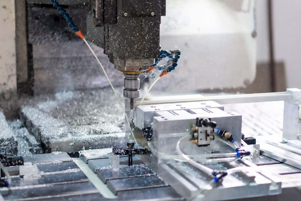
CNC milling removes material from a solid block with a rotating cutter under computer control. On CutLinq you upload a STEP file, choose the material and finish, and receive a binding quote within 12 hours from a workshop in Egypt, the UAE or Saudi Arabia. Standard tolerance is ±0.05 mm; ±0.01 mm is achievable on critical features when the drawing calls for it. Typical parts are housings, brackets, fixtures, manifolds, mould inserts and one-off replacement parts.
This page explains what 3, 4 and 5-axis milling can and cannot do, which materials and tolerances are realistic, how to design a part so it machines cheaply, and what drives lead time. It applies equally to a single prototype and to batches of several hundred.
3-axis, 4-axis and 5-axis: what changes
A 3-axis machine moves the cutter in X, Y and Z. It handles most brackets, plates and pocketed housings, but every face that needs machining requires a separate setup. Each setup adds time and a small alignment error, typically 0.02 to 0.05 mm between faces.
4-axis adds a rotary axis, usually along X, so cylindrical parts, shafts with flats or parts with features on four sides can be machined in one clamping. 5-axis tilts the spindle or the table so undercuts, compound angles and impeller-type geometry are reachable without re-fixturing. 5-axis hourly rates are higher, but for a part with six machined faces the total cost is often lower because setups drop from three or four to one.
| Machine type | Typical work envelope | Setups for a 6-face part | Positional accuracy between faces | Best for |
|---|---|---|---|---|
| 3-axis vertical | up to 1000 x 500 x 500 mm | 3 to 4 | ±0.03 to ±0.05 mm | plates, brackets, pockets, simple housings |
| 4-axis | up to 800 x 400 x 400 mm | 1 to 2 | ±0.02 to ±0.03 mm | shafts with flats, manifolds, indexed holes |
| 5-axis | up to 600 x 600 x 500 mm | 1 | ±0.01 to ±0.02 mm | compound angles, undercuts, impellers, mould cores |
Materials and machinability
Aluminium is the fastest and cheapest to mill; steel and stainless take two to four times longer per unit of removed volume; titanium and PEEK longer still. Machinability ratings below are relative to free-cutting brass at 100.
In the Gulf climate, aluminium and stainless parts are stored and shipped without rust concern. Mild steel parts should be oiled or coated before delivery, especially in coastal Alexandria, Dubai and Dammam where salt humidity starts surface rust within days.
| Material (EN / common) | Relative machinability | Relative cost per part vs 6061 | Notes |
|---|---|---|---|
| EN AW-6061-T6 / EN AW-6082 | 90 | 1.0 | default choice, anodises well |
| EN AW-7075-T6 | 80 | 1.3 to 1.5 | high strength, poor weldability |
| S235JR / S355J2 (mild steel) | 60 | 1.4 to 1.8 | oil or coat after machining |
| 42CrMo4 (4140) | 55 | 1.8 to 2.2 | shafts, gears, pre-hardened option |
| 1.4301 (304) | 45 | 2.0 to 2.5 | work-hardens, needs rigid setup |
| 1.4404 (316L) | 40 | 2.5 to 3.0 | coastal and food applications |
| CuZn39Pb3 (free-cutting brass) | 100 | 1.5 to 2.0 | material cost dominates |
| POM-C / PEEK | 80 / 50 | 0.9 / 4 to 6 | burr control, thermal expansion |
| Ti Grade 5 (Ti-6Al-4V) | 20 | 6 to 10 | low speeds, carbide tooling |
Tolerances and surface finish
Unless your drawing says otherwise, parts are made to ISO 2768-m (medium) for linear dimensions and ISO 2768-K for geometry. That gives ±0.1 mm on dimensions from 6 to 30 mm and ±0.2 mm from 30 to 120 mm. Tightening individual features to ±0.05 mm costs little; asking for ±0.01 mm on a bore means slower feeds, in-process gauging and often a reaming or boring operation, so specify it only where a bearing or dowel needs it.
Surface finish from a standard milling pass is Ra 1.6 to 3.2 µm. A finishing pass with a fine stepover reaches Ra 0.8 µm. Below that you need grinding, lapping or polishing.
| Feature | Standard | Tight (on request) | Cost effect |
|---|---|---|---|
| Linear dimension | ±0.1 mm (ISO 2768-m) | ±0.01 to ±0.02 mm | +15 to +40% on that feature |
| Bore diameter (reamed) | H9 | H7 | +10 to +20% |
| Flatness per 100 mm | 0.1 mm | 0.02 mm | requires stress relief on steel |
| Surface roughness | Ra 3.2 µm | Ra 0.8 µm | +10 to +25% on machining time |
| Thread (tapped) | 6H | 6H, gauge checked | small |
Designing for lower milling cost
The largest hidden cost in milling is small internal radii. A pocket corner radius of 1 mm forces a 2 mm cutter, which must run slowly and take shallow passes. Increasing the radius to 4 mm allows an 8 mm cutter that removes material roughly ten times faster. Similarly, pocket depth should not exceed four times the cutter diameter, so a 30 mm deep pocket needs at least 8 mm corner radii.
Thin walls below 1 mm in aluminium and 1.5 mm in steel deflect and chatter. Keep walls at 1.5 mm or more, floors at 1 mm or more, and avoid deep narrow slots. Standardise hole sizes to drill diameters (M3, M4, M5, M6, M8 tapping drills and 6, 8, 10, 12 mm dowel reamers) so no custom tooling is needed.
Finishing after milling
Aluminium parts are usually deburred and either left as-machined, bead blasted (matt, hides tool marks) or anodised type II at 5 to 25 µm in clear, black or a colour. Steel parts are typically black oxide, zinc plated 5 to 12 µm, or powder coated 60 to 120 µm. Stainless is passivated or electropolished. All finishes are ordered on the same quote.
- As-machined: Ra 1.6 to 3.2 µm, visible tool paths, cheapest
- Bead blast: uniform matt, adds one working day
- Anodising type II: 5 to 25 µm, adds 2 to 4 working days, dimensions grow by about half the coating thickness per side
- Hard anodising type III: 25 to 50 µm for wear surfaces, dimensions grow by about 50% of the thickness per side
- Zinc plating: 5 to 12 µm, mask threads or re-tap after plating
- Powder coating: 60 to 120 µm, mask precision bores and threads
Design tips
- Use internal corner radii of at least 3 mm, and at least one third of the pocket depth for deep pockets.
- Keep pocket depth under 4 times the cutter diameter; a 40 mm deep pocket needs 10 mm cutter and 5 mm or larger corner radius.
- Wall thickness: minimum 1.5 mm in aluminium, 2 mm in steel and stainless, 2.5 mm in plastics.
- Specify ±0.1 mm general tolerance (ISO 2768-m) and tighten only bearing bores and dowel holes to H7.
- Design blind holes 1.5 mm deeper than the required thread length to leave room for the tap chamfer.
- Limit thread depth to 2 times the nominal diameter; an M6 thread deeper than 12 mm adds no strength.
- Provide a STEP file plus a PDF drawing with critical dimensions; a STEP alone is quoted at ISO 2768-m.
Applications
| Industry | Example parts | Typical material |
|---|---|---|
| Machinery and OEM | gearbox housings, bearing blocks, jigs | 6061-T6, 42CrMo4 |
| Oil and gas | manifold blocks, valve bodies, flanges | 1.4404 (316L), 42CrMo4 |
| Electronics and enclosures | heat sinks, chassis, RF housings | 6061-T6, 6082 |
| Automotive aftermarket | adapter plates, hubs, brackets | 7075-T6, S355J2 |
| Medical and laboratory | instrument bodies, fixtures | 1.4404 (316L), POM-C, PEEK |
| Solar and energy | tracker components, clamps | 6061-T6, 1.4301 (304) |
| Packaging machinery | guides, cams, change parts | POM-C, 6082, 1.4301 (304) |
Pricing and lead time
Three factors set the price of a milled part: machining time (driven by removed volume, smallest corner radius and tightest tolerance), number of setups (each extra face adds fixture time), and material (stock cost plus how slowly it cuts). A 100 x 60 x 20 mm aluminium bracket with four holes and one pocket is quoted as a benchmark of 1.0; the same part in 304 stainless costs roughly 2.0 to 2.5, in 316L about 2.5 to 3.0, and ordering 20 instead of 1 typically halves the unit price because programming and setup are spread across the batch. Lead time is 3 to 5 working days for simple aluminium parts, 5 to 8 working days for steel and stainless or multi-setup parts, plus 2 to 4 working days for anodising or plating. Delivery within Cairo, Dubai, Riyadh and the main industrial zones is usually next day by courier.
Frequently asked questions
For simple parts yes, but a STEP file gets you a binding quote within 12 hours and avoids interpretation errors. If you only have a PDF, send it and we will confirm whether the workshop needs a model built first, which adds one to two working days.
Upload your STEP file, select material and finish, and receive a binding CNC milling quote within 12 hours.