Design for CNC Milling: Pockets, Radii and Wall Thickness
Practical rules for pocket depth, internal corner radii and minimum wall thickness that keep machining time and cost down
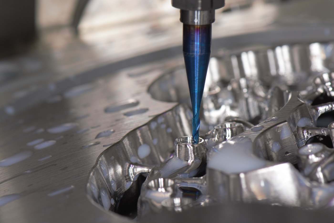
CNC milling can cut almost any 2.5D or 3D geometry from a solid block, but every feature that deviates from a standard tool shape adds machining time and cost. Deep narrow pockets, sharp internal corners and thin unsupported walls are the three features most likely to make a part slow, expensive or impossible to hold to tolerance.
This page gives numeric rules for pocket depth, corner radii and wall thickness in aluminium and steel, with a worked example showing how one design change cut machining time by 40%.
Pocket depth and aspect ratio
A pocket cut with an end mill of diameter D can typically reach a depth of 3 to 4 times D before tool deflection and chip evacuation start degrading surface finish and dimensional accuracy. A 6 mm end mill can comfortably cut an 18-24 mm deep pocket; pushing to 40 mm depth with the same tool requires slower feeds, more passes, and accepts a rougher wall finish.
For a pocket 10 mm wide, the largest end mill that fits with clearance is about 8-9 mm, limiting practical depth to roughly 25-35 mm before needing a specialised long-reach tool, which costs more and deflects more under load.
| Pocket width | Max practical tool diameter | Recommended max depth | Note |
|---|---|---|---|
| 5 mm | 4 mm | 12-16 mm | Standard end mill |
| 10 mm | 8-9 mm | 25-35 mm | Standard end mill |
| 20 mm | 16-18 mm | 60-70 mm | Standard end mill |
| 50 mm | 40-45 mm | 150-180 mm | Standard end mill |
Internal corner radii
A milling cutter is round, so it cannot produce a sharp internal corner. The minimum internal radius equals the radius of the smallest practical cutter for that pocket depth -- for a 10 mm deep pocket machined with an 8 mm end mill, the internal corners will show a 4 mm radius unless a smaller tool is used to clean up the corner in a separate, slower pass.
Specifying an internal radius larger than the minimum forced by the pocket geometry, for example 3 mm instead of the minimum 1 mm, allows a larger, more rigid tool to be used and can cut machining time by 20-30% on pocket-heavy parts. Mating parts (a shaft into a pocket corner) should be relieved with a chamfer or undercut rather than requiring the pocket corner to be sharp.
| Design choice | Effect on cost and time |
|---|---|
| Internal radius = pocket depth / 4 (matches standard tool) | Baseline cost |
| Internal radius smaller than needed for a rigid tool | +15-30% machining time, risk of tool deflection marks |
| Internal radius generous (2-3x minimum) | -10-20% machining time, better surface finish |
| Sharp internal corner required by mating part | Add relief chamfer on mating part instead |
Minimum wall thickness
Thin walls flex under cutting force, producing chatter marks and dimensional error, especially on tall unsupported walls in aluminium. As a rule of thumb, a wall height-to-thickness ratio above 10:1 in aluminium (6061-T6) needs reduced cutting parameters and may still show 0.05-0.1 mm of deflection; in steel the same ratio is more forgiving due to higher stiffness, tolerating closer to 15:1 before special care is needed.
A 2 mm aluminium wall standing 15 mm tall (7.5:1 ratio) machines reliably to standard tolerance. The same wall at 25 mm tall (12.5:1) will typically need a slower finishing pass and may still deviate 0.03-0.08 mm from nominal at the top.
| Material | Safe height:thickness ratio | Caution zone | Note |
|---|---|---|---|
| Aluminium 6061-T6 | up to 8:1 | 8:1 to 12:1 | Above 12:1, add support ribs or reduce height |
| Mild steel S235JR | up to 12:1 | 12:1 to 15:1 | Stiffer material tolerates more |
| Stainless 1.4301 (304) | up to 10:1 | 10:1 to 14:1 | Work hardens; use sharp tools |
| Engineering plastics (POM, PA) | up to 6:1 | 6:1 to 10:1 | Heat buildup causes deflection |
Worked example: a bracket with four deep pockets
An original design specified four 12 mm wide, 45 mm deep pockets with 1 mm internal corner radii in 6061-T6 aluminium. This forced a 10 mm end mill (leaving 1 mm clearance) working at a 4.5:1 depth ratio near its practical limit, plus a separate 2 mm tool pass to clean the 1 mm corners -- two tool changes per pocket and reduced feed rates to control deflection.
Increasing the corner radius to 3 mm and reducing pocket depth to 30 mm (still meeting the functional requirement) allowed a single 10 mm end mill to complete each pocket in one operation at full feed rate. Measured machining time dropped by about 40% and surface finish improved from Ra 3.2 to Ra 1.6 without added cost.
Design tips
- Set internal corner radii to at least pocket depth divided by 4, or 1.5-2 times the minimum forced radius, whichever is larger.
- Keep pocket depth-to-tool-diameter ratio under 4:1 for standard tooling; beyond that, expect a cost and time premium for long-reach tools.
- Keep wall height-to-thickness ratio under 8:1 in aluminium and 12:1 in steel unless the application specifically needs a taller thin wall.
- Add a 0.5-1 mm chamfer on all sharp external edges; this is standard practice and removes machining burrs without extra cost.
- Avoid specifying flat-bottomed pockets deeper than 4x the corner radius without a draft or relief; tool deflection at full depth degrades flatness.
- Where a mating part needs a sharp internal corner, put the relief chamfer on the mating (usually simpler) part rather than forcing a small-radius pocket.
- For thin-wall parts in plastic (POM, PEEK), reduce wall height-to-thickness target by about 30% versus the aluminium rule due to heat sensitivity.
Applications
| Industry | Example parts | Typical material |
|---|---|---|
| Machinery and OEM | Housings with internal pockets, gearboxes | 6061-T6, S235JR |
| Aerospace-adjacent and precision | Lightweight brackets, ribbed panels | 6061-T6, 7075-T6 |
| Plastics and moulding | Mould cavities, ejector plates | 1.2311 (P20), POM |
| Medical and lab equipment | Enclosures, instrument housings | 1.4301 (304), 6061-T6 |
| Electronics and enclosures | Chassis with cable channels | 6061-T6, 5052 |
| Automotive tooling | Fixture plates, jig bodies | S235JR, C45 |
Pricing and lead time
Milling cost is driven by material removal volume and depth-to-diameter ratio (deep narrow pockets need slower feeds and more passes), by the number of setups and tool changes required (generous radii and shallower pockets reduce tool changes), and by tolerance and surface finish requirements (tight tolerances under ±0.02 mm add finishing passes and inspection time). Simple pocketed parts in aluminium ship in 3-5 working days; complex multi-setup parts with tight tolerances in 7-12 working days.
Frequently asked questions
A sharp corner cannot be cut by a round tool; the shop either uses a much smaller, slower tool for the whole pocket or adds a separate corner-clearing operation. A 2-3 mm radius instead of a sharp corner is usually free to machine.
Upload a STEP file and we will flag any pocket, radius or wall-thickness issue before quoting, with a binding quote within 12 hours.