Design for CNC Turning: Shafts, Grooves and Threads
Practical rules for shafts, bores, grooves and threads that keep lathe-turned parts fast and accurate
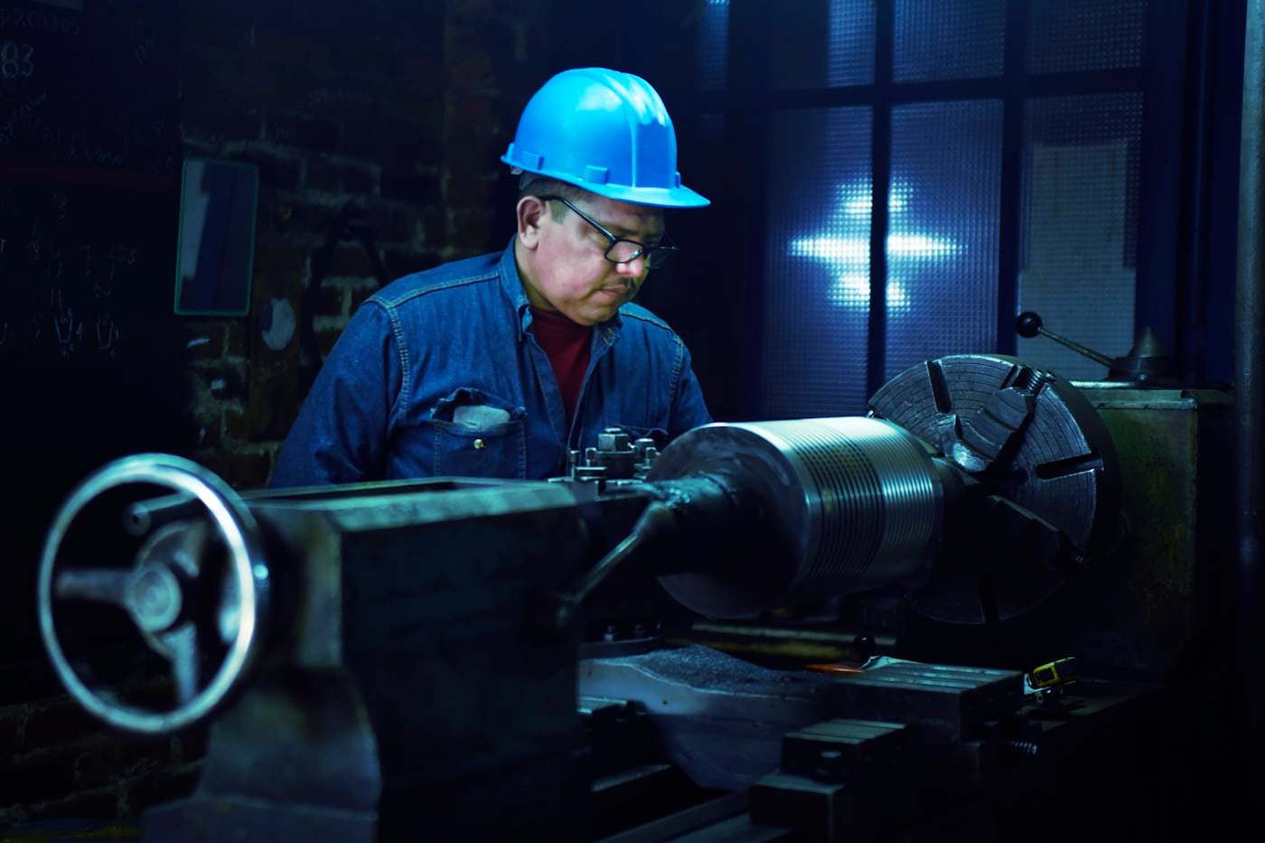
CNC turning produces round parts such as shafts, bushings and fittings by rotating stock against a cutting tool. Designing within the process's natural limits (length-to-diameter ratio, groove and thread relief geometry, achievable tolerance) avoids chatter, tool deflection and rejected parts. A shaft that ignores these limits can cost double to machine and still miss tolerance.
This guide covers the numeric rules for shaft proportions, undercuts, threads and surface finish, with a worked example, followed by what to send CutLinq for a turning quote.
Length-to-diameter ratio
A turned shaft held only in a chuck without tailstock support should keep its length-to-diameter (L/D) ratio below 3:1 to avoid deflection and chatter. With tailstock or steady-rest support, L/D up to 10:1 is workable, but feed rates must slow as the ratio increases.
Beyond L/D of roughly 12:1, whip and taper become difficult to control even with support, and the part may need centre-drilling at both ends or a different process.
| L/D ratio | Support needed | Practical result |
|---|---|---|
| under 3:1 | chuck only | good tolerance, fast |
| 3:1 to 10:1 | tailstock/steady rest | workable, slower feed |
| over 12:1 | special fixturing | taper and whip risk |
Grooves, undercuts and thread relief
External grooves should be at least 1.5 mm wide to allow standard grooving tools; narrower grooves require custom tooling and add cost. Where a thread meets a shoulder, add a thread relief groove at least 1x the thread pitch wide so the tool can retract cleanly without leaving a partial thread.
Internal bores under 6 mm diameter limit tool access and increase deflection risk; where possible, keep internal bore diameter above 8 mm for depths beyond 3x diameter.
| Feature | Minimum practical size |
|---|---|
| External groove width | 1.5 mm |
| Thread relief width | 1x thread pitch |
| Internal bore (deep) | 8 mm diameter for depth > 3x D |
| Chamfer on edges | 0.3-0.5 mm x 45 degrees |
Threads and tolerance
Standard metric threads (M3 to M24) are cut directly on the lathe or added with a die/tap after turning; single-point threading on the lathe is more accurate for load-bearing threads. Standard turning tolerance on diameters is ±0.05 mm; tolerances down to ±0.01 mm are achievable on critical diameters such as bearing seats but add cost and inspection time.
Concentricity between turned diameters on the same part is typically held to 0.02-0.05 mm when machined in one setup without removing the part from the chuck.
Worked example: a stepped shaft
A 6061-T6 aluminium shaft, 12 mm diameter and 90 mm long (L/D = 7.5), needs tailstock support. It has an M8 thread at one end with a 2 mm thread relief groove, a 0.05 mm tolerance on the bearing seat diameter, and 0.5 mm x 45 degree chamfers on all ends. This geometry machines in one setup with standard tooling, avoiding the cost of custom grooving tools or a second chucking operation.
Design tips
- Keep L/D ratio under 3:1 for chuck-only turning; use tailstock support up to 10:1.
- Make external groove width at least 1.5 mm to use standard grooving inserts.
- Add a thread relief groove at least 1x pitch wide before any shoulder.
- Specify ±0.05 mm tolerance by default; reserve ±0.01 mm for bearing or sealing diameters only.
- Chamfer all sharp edges 0.3-0.5 mm x 45 degrees to avoid burrs and ease assembly.
- Keep internal bores above 8 mm diameter when depth exceeds 3x the bore diameter.
- Design the part to be finished in one chucking where possible to hold concentricity within 0.02-0.05 mm.
Applications
| Industry | Example parts | Typical material |
|---|---|---|
| Machinery OEM | Shafts, bushings | S235JR, 6061-T6 |
| Automotive aftermarket | Spacers, pins | Mild steel, brass |
| Electrical | Standoffs, connectors | Brass CuZn37 |
| Oil and gas | Fittings, adapters | 316L stainless |
| Furniture | Threaded feet, pins | 6061-T6 aluminium |
| Medical/lab | Precision shafts | 316L, titanium Grade 5 |
Pricing and lead time
Turned part cost is driven by three factors: material and bar-stock diameter, machining time (length, number of diameter steps, thread cutting), and tolerance on critical diameters. Lead time for standard turned parts runs 4-7 working days; parts needing tight bearing-fit tolerances or secondary grinding typically take 7-10 working days.
Frequently asked questions
Without support, keep length under 3 times the diameter; with tailstock or steady-rest support, up to 10 times the diameter is workable at slower feed rates.
Upload a STEP file of your shaft or turned part to receive a binding quote within 12 hours.