ISO 2768 General Tolerances Explained
How the four ISO 2768-1 tolerance classes work, when to call one out, and when a tighter dimension needs its own tolerance
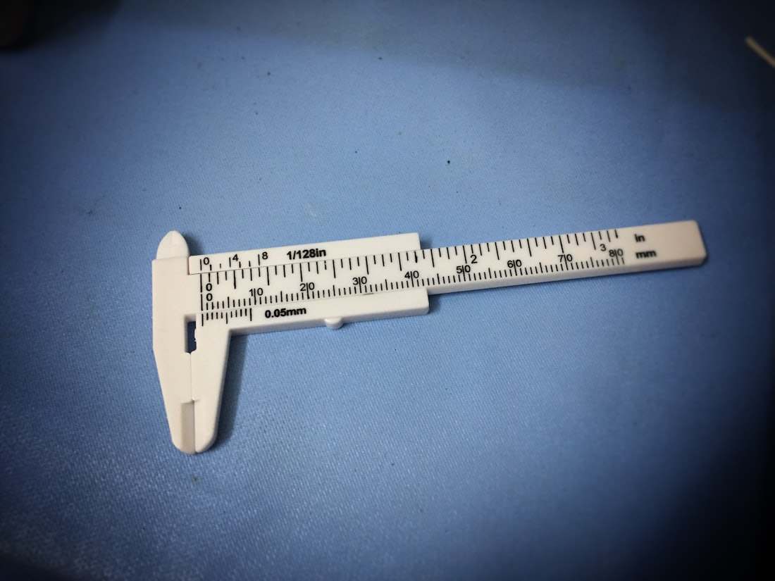
ISO 2768 is the general tolerance standard that applies to any dimension on a drawing that does not carry its own explicit tolerance; it sets four classes, fine (f), medium (m), coarse (c) and very coarse (v), each with a table of permitted deviation by dimension range. Calling out a single ISO 2768 class in the drawing title block replaces dozens of individual ± callouts on non-critical dimensions and is standard practice on sheet metal and machined part drawings across the region.
This page gives the linear and angular tolerance tables for all four classes, explains which class fits laser-cut, bent and CNC-machined parts, and shows a worked example of when a dimension needs its own tighter tolerance instead of relying on the general class.
ISO 2768-1 linear tolerance classes
ISO 2768-1 covers linear and angular dimensions without individual tolerance indication. The permitted deviation grows with the nominal dimension: a 10 mm feature and a 1000 mm feature under the same class carry very different absolute tolerance in millimetres, since manufacturing error scales with size for most processes.
Class m (medium) is the default assumed on most commercial drawings when no class is stated, and is a reasonable match for standard CNC machining and laser-cut sheet metal. Class f (fine) suits tighter general machining; class c (coarse) suits basic fabrication and welded structures; class v (very coarse) is rarely used outside rough construction steelwork.
| Dimension range (mm) | f (fine) | m (medium) | c (coarse) | v (very coarse) |
|---|---|---|---|---|
| 0.5-3 | ±0.05 | ±0.1 | ±0.2 | - |
| 3-6 | ±0.05 | ±0.1 | ±0.3 | ±0.5 |
| 6-30 | ±0.1 | ±0.2 | ±0.5 | ±1.0 |
| 30-120 | ±0.15 | ±0.3 | ±0.8 | ±1.5 |
| 120-400 | ±0.2 | ±0.5 | ±1.2 | ±2.5 |
| 400-1000 | ±0.3 | ±0.8 | ±2.0 | ±4.0 |
| 1000-2000 | ±0.5 | ±1.2 | ±3.0 | ±6.0 |
Angular tolerances (ISO 2768-1)
Angular tolerance under ISO 2768-1 is expressed per class and depends on the length of the shorter side of the angle, not the nominal angle itself; a longer leg gives a tighter angular tolerance because the same linear deviation over a longer arm represents a smaller angle.
| Shorter side length (mm) | f (fine) | m (medium) | c (coarse) | v (very coarse) |
|---|---|---|---|---|
| up to 10 | ±1° | ±1° | ±1°30' | ±3° |
| 10-50 | ±0°30' | ±0°30' | ±1° | ±2° |
| 50-120 | ±0°20' | ±0°20' | ±0°30' | ±1° |
| 120-400 | ±0°10' | ±0°10' | ±0°15' | ±0°30' |
| over 400 | ±0°5' | ±0°5' | ±0°10' | ±0°20' |
ISO 2768-2: form and position tolerances
A second part of the standard, ISO 2768-2, covers form and position tolerances (straightness, flatness, perpendicularity, symmetry, runout) in two classes, H and K, used together with a linear class (e.g. '2768-mK'). It is used less often than part 1 in general fabrication drawings and is mainly relevant to precision machined parts where flatness or perpendicularity matters beyond the linear dimension itself.
When to override with an individual tolerance
Any dimension that controls a fit, a mating surface, a bearing bore, a sealing groove or an assembly clearance should carry its own explicit tolerance rather than relying on the general class; ISO 2768 class m at ±0.2 mm on a 30 mm bore is far looser than a bearing press-fit typically needs (often ±0.01-0.02 mm). Leaving a functional dimension to the general class is one of the most common causes of assembly rework.
Worked example
A CNC-machined bracket, 250 mm long, drawn with ISO 2768-mK in the title block and no individual tolerances except one 20H7 bore for a bearing: the 250 mm overall length falls in the 120-400 mm range at class m, giving ±0.5 mm, which is adequate for a bracket that only needs to fit inside an enclosure. The 20H7 bore, however, is individually toleranced to +0.021/0 mm because it locates a bearing and the general class would be roughly 25 times looser than the fit requires.
Design tips
- State an ISO 2768 class in every drawing title block; if none is stated, class m is what most shops will assume by default.
- Use class m for standard laser-cut and bent sheet metal and general CNC machining; reserve class f for tighter general work.
- Override the general class with an individual tolerance on any bore, shaft, sealing face or mating dimension.
- Do not specify class f or finer as a blanket tolerance across an entire drawing if only a few features need it; it raises cost on every other dimension too.
- Remember angular tolerance under ISO 2768-1 depends on the shorter leg length, not the angle value, when checking a drawing against the standard.
- For bent sheet metal, note that ISO 2768 linear tolerances do not directly cover bend angle; specify bend angle tolerance separately (commonly ±0.5°).
- Combine ISO 2768-1 (linear/angular) with ISO 2768-2 (form/position, e.g. mK) only when flatness or perpendicularity is functionally important.
Applications
| Industry | Example parts | Typical ISO 2768 class |
|---|---|---|
| Sheet metal enclosures | Brackets, panels, chassis | m (medium) |
| General CNC machining | Housings, plates, shafts (non-critical dims) | m (medium), f on mating features |
| Structural and welded steelwork | Base plates, frames, gussets | c (coarse) |
| Precision machined parts | Bearing housings, gauge components | f (fine), individual tolerances on fits |
| Construction steelwork | Rough weldments, site-assembled frames | v (very coarse) |
| Machinery and OEM parts | Structural brackets, covers | m (medium) |
| Medical and lab equipment | Instrument housings, mounts | f (fine), individual tolerances common |
Pricing and lead time
Cost is driven by which tolerance class is specified (class f across an entire part raises machining time and inspection cost compared with class m or c, since more passes and tighter measurement are needed), by how many features carry individual tolerances outside the general class (each individually toleranced feature adds inspection time), and by part size (larger parts holding a fine class are proportionally harder to achieve). Standard class m parts follow normal lead times of 3-6 working days for sheet metal or 5-8 for machining; class f parts or parts with several individually toleranced features can add 1-3 working days for additional inspection.
Frequently asked questions
Most shops default to ISO 2768-m (medium) when nothing is stated, but this is a risky assumption to leave unstated; put the class explicitly in the title block so the quote and inspection match your expectation.
Upload your DXF or STEP file with the ISO 2768 class stated and receive a binding quote within 12 hours.